Showing posts with label cnc. Show all posts

Monday, April 2, 2012

Andrew F. Scott: Laser Scanning To Milling


This is a keyshot rendering of a relief sculpture that incorporates laser scanned data. The model was scanned using a Next Engine Scanner. The data was processed using Rapid Works reverse engineering software. This workflow outlines how RapidWorks can be used to generate a variety of nurbs surfaces. While the focus of this posting is on  the CNC milling process, the same workflow can be used for FDM and Laser Cutting Operations.
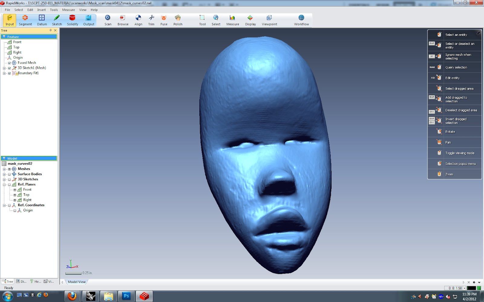

Once Scanned the data is brought into RapidWorks where it is cleaned up and prepared for both surfaces decimation which is used to generate polygonal data and a variety of operations that are used to generate surfaces. Using the AutoSurfacing function Rapidworks can generated two types of surfaces.

This is an example of a surface that is generated using an evenly distributed network of patches. Using this function will overlay a net-like surface of user defined quad patches that does not adhere to the contours of your object. The net like structure follows and adheres to the typology of the surface. Each patch has a user defined number of control points that is used to control the complexity of the patch network.

The Feature Following Network tries to follow the typology of your object more closely by generating a series of quad patches based on the contours of your objects. There are a variety of settings that can be adjusted to achieve different effects using this option. The main two focus on are Feature Detection Level and Geometry Capture Accuracy.


For the greatest degree of control and artistic expression you can draw your own patch typology on the object using the 3D Sketch Mode. This mode has a variety of tools for generating your patch typology on top of your mesh object. Above is a quick sketch of a patch network that I drew on the scanned model. As an edge loop disciple I will probably go back and redo the network so that the edge loops reflect the true contours of the model. This is important because these lines can be used to generate surface details as shown in an earlier posting of my fist model that focused on nurbs modeling and laser scanning.

I am very excited about this branch of research because it affords total control over the surface typology of scanned models. You can generate almost any surface pattern you want as long as it is composed of quadrilateral patches. The software will also generate boundary surfaces when you use 3-sided patches or patches with more than four sides. It prefers quad patches.


The patches are easily joined in Rhino into a polysurface. It is also easier to fix problem patches using the surface generation tools within Rhino. Once done your model can be incorporated into a variety of modeling techniques.


I am interested in exploring the potential of the scanned data using a variety of milling techniques that focus on surface typologies and its influence on the texture of the objects. This is only the beginning.

Tuesday, March 15, 2011

Ricki Dwyer: Plastic Quilt


With my CNC milling project, I vacuum formed my relief with painters tarp. This material is more or less industrial strength trash bags, very pliable before and after the vacuum forming process. I had to cut my relief down into quarters, and ended up only using one of the quarters I had milled, due to aesthetic choices. I vacuum formed thirty squares and ironed the white binding on to adhere the plastics together. This quilt is the standard size of a twin bed.

Ricki Dwyer: CNC Quilt Block


Using the CNC milling machine, I created this relief based on a traditional colonial quilt pattern out of yellow foam.

Wednesday, November 17, 2010

john mcmahon: teef(3D scanning)

i never messed with a 3D scanner before
so that was something i definitely wanted to test out
for my first scan i wanted to keep it simple
was searching for an object to scan and came across
my friend sam's car sculpture that was laying around
scanned the car but at a super high resolution
which didn't leave much room on the computer to complete the steps for outputting
after referring with prof. scott, he told me to step the res. down
so i scanned my teeth(a plaster model of my teeth)
the goal was to scan the uppers and lowers and alter them
and output to the wax printer in the jewerly building
but once i over came the scanning process
i ran into some issues with offsetting the surfaces to create digital "fronts"
the offset that the wax printer needed to meet the minimum output
was to much for rapidworks and rhino to do a simple offset
the larger offset was producing self intersecting surfaces
a no no in rapid prototyping
need more time to troubleshoot through this issue


madebymixta

john mcmahon: Corrugation - Plica cont.

got caught up in the rush so there is a lil gap in the pics
painting, cement casting and acrylic bending was not recorded
but i have the jig i used for bending the extruded acrylic rods
and then i jump right to the presentation pics, fdm 1/4 scale model,
and model in context(museum)


Wednesday, September 29, 2010

Brandy Koch: Gun Crazy

Well here is a blip of my head and thinking, I love guns, so this is my first go at it on the computer. Rhino is all new to me and I have been loving it!! I had to re-start a few times, as I would learn more from the tutorials and class as to better ways of handleing the problems that arose. Over all I cant wait to see it milled and I look forward to using this program again!!


Wednesday, September 22, 2010

Christian Dunbar - Project 1 - Sculpted Wave


In project 1, I set out to create a depiction of fluid movement by sculpting a solid material. The material I would be using was a 14 x 6 x 48 block of wood. First, I drew out a series of curves, that I would eventually use in conjunction with the loft command, to create a surface. My aim was to create a "water-like" shape, with an unknown being underneath, creating a wave. Next, I began lofting the surface. During this careful process, I manipulated several variables: control points of each curve, curve placement and coordination, number of surface control points, and various loft styles and simplification levels. Through hours of shaping and lofting and after many undesirable results, I ultimately designed a surface that created the desired effect. Next, I was faced with creating a solid from the surface. To do so, I created a solid box, and used my surface as a slicing tool with the Boolean split method. Finally, I used the scale command to fit my solid to the exact shape of my wood block. Ultimately, I was left with a solid positive and a solid negative for future prototyping and casting.

Andrea Lucas: Ring


First Keyshot Modeling

Brandy Kennedy Koch-Blog Test


Shannon Slane:Connected


Connected. Shannon Slane. CNC milled foam, gesso, iron pipes. 2010.

Shannon Slane incorporated CNC milled foam relief elements into this sculptural composition "Connected". The reliefs were created using the heightfield surface displacements in Rhino. The greyscale images were processed in photoshop. It's nice to see this come together in its completed form. This is yet another example of how digital fabrication can be combined and seamlessly integrated into tradiional sculptural processes. To view videos of the elements in progress on the mill visit my youtube channel andrewfscott. They are entitled "crybaby' and cow. A big thank you goes out to Bob Delli Bovi for his help in a pinch this summer.


Wednesday, August 25, 2010

David Markus | Milling Project Update

I was extremely pleased with how my milling project came out. I was afraid that the channels might be too deep or that odd angles might be difficult for the CNC to fabricate, but was surprised to find that everything came out extraordinarily well

I decided to use metallic gray automotive paint, but before that I had to prime and fill the porous yellow foam to prepare it for spraying.

I then put down my base coat of BMW metallic grey.


Before finally spraying a heavy layer of clear-coat to complete it.


Tuesday, August 24, 2010

Tamela Sicay-Perrow Progress Report

While continuing to work along with project's 1 and 2, the processes which I used are as follows. For the yellow foam cnc'd project, I coated the surface with a mixture of acetone and spot putty from an autoparts store, these form a seal after several coats. After letting it dry completely, and with minimal sanding I was able to coat the form with a smooth-on mixture to create a flexible mold.
This is what the mold looks like after complete drying to demold the original part. It is now ready to pour in whatever moldable liquid you might want to use, such as plaster, hot wax, or resin. This entire process doesn't need a mold release agent, and while messy, is less than expected.
Products used: yellow high density foam, plaster, burlap, smooth-on rebound 25, 100 percent pure acetone, and Dynatron glazing and spot putty.