Showing posts with label project1milling. Show all posts

Tuesday, April 3, 2012

Andrew F. Scott: Material Studies


Scanned Rhino Model in rhino

I had the opportunity to do a little more form exploration on the previous model from laser scanned data.  Within Rhino I used the nurbs surface tessellation as a cue for the surface activation of the model. Using pipes i created a series of sweeping linear forms across the surface of the model.
Mahogany


Polished Oak
I began with a series of monochromatic compositions using a single material I wanted to get a feel for the rhythmic movement of the lines across the surface of the material.


Mahogany with Cherry
 This led to an exploration of a combination of materials. This is where the fun really begins as you can begin to play material properties with and against each other.

Gold with Pearl
 I really like this combination of materials because it begins to suggest a form that can operate on a diversity of scales.
Gold with Mahogany


Monday, April 2, 2012

Andrew F. Scott: Laser Scanning To Milling


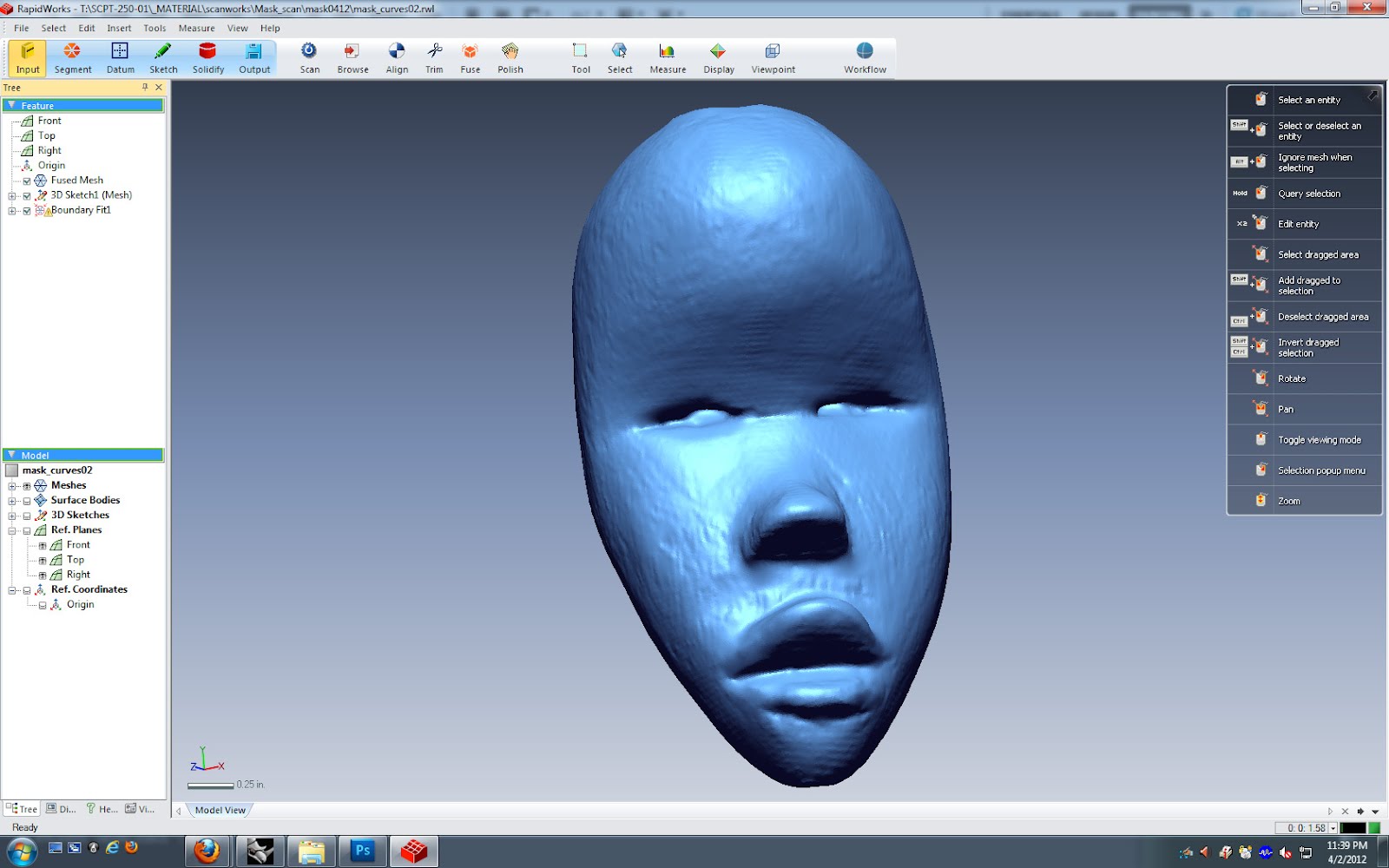
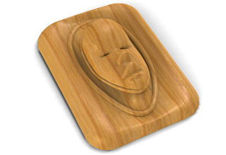
This is a keyshot rendering of a relief sculpture that incorporates laser scanned data. The model was scanned using a Next Engine Scanner. The data was processed using Rapid Works reverse engineering software. This workflow outlines how RapidWorks can be used to generate a variety of nurbs surfaces. While the focus of this posting is on  the CNC milling process, the same workflow can be used for FDM and Laser Cutting Operations.

Once Scanned the data is brought into RapidWorks where it is cleaned up and prepared for both surfaces decimation which is used to generate polygonal data and a variety of operations that are used to generate surfaces. Using the AutoSurfacing function Rapidworks can generated two types of surfaces.
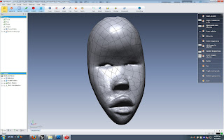
This is an example of a surface that is generated using an evenly distributed network of patches. Using this function will overlay a net-like surface of user defined quad patches that does not adhere to the contours of your object. The net like structure follows and adheres to the typology of the surface. Each patch has a user defined number of control points that is used to control the complexity of the patch network.
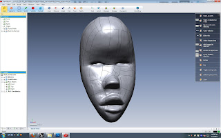
The Feature Following Network tries to follow the typology of your object more closely by generating a series of quad patches based on the contours of your objects. There are a variety of settings that can be adjusted to achieve different effects using this option. The main two focus on are Feature Detection Level and Geometry Capture Accuracy.
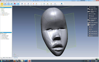

For the greatest degree of control and artistic expression you can draw your own patch typology on the object using the 3D Sketch Mode. This mode has a variety of tools for generating your patch typology on top of your mesh object. Above is a quick sketch of a patch network that I drew on the scanned model. As an edge loop disciple I will probably go back and redo the network so that the edge loops reflect the true contours of the model. This is important because these lines can be used to generate surface details as shown in an earlier posting of my fist model that focused on nurbs modeling and laser scanning.

I am very excited about this branch of research because it affords total control over the surface typology of scanned models. You can generate almost any surface pattern you want as long as it is composed of quadrilateral patches. The software will also generate boundary surfaces when you use 3-sided patches or patches with more than four sides. It prefers quad patches.
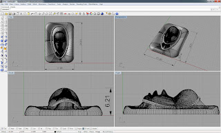

The patches are easily joined in Rhino into a polysurface. It is also easier to fix problem patches using the surface generation tools within Rhino. Once done your model can be incorporated into a variety of modeling techniques.


I am interested in exploring the potential of the scanned data using a variety of milling techniques that focus on surface typologies and its influence on the texture of the objects. This is only the beginning.

Friday, October 15, 2010

Andrea Lucas: Project 1 Milling Update


The CNC did three passes with different sized drill bits for this project. It was all cut in approximately one hour. The high density foam held its form perfectly, though to get into the valleys, sharp V-cuts were not possible, so the design was distorted, very very slightly. All in all, it was pretty exciting to see it cut. (Thanks Bob)

Wednesday, July 14, 2010

Tamela Sicay-Perrow Project 1 CNC Mill

I have completed the first step in Project 1, a 3d model from which a block of yellow polyurethane foam will be milled out and later molded. Thematically, these are an abstraction of a fruit or melon. Poured casts will be grouped together, and arranged for the final piece. This mould can also be combined to create fully round melon type objects, or partials.
The models were created by manipulating control-points or CV's in Rhino, from perfect spheres to shapes with symmetrically spaced ridges.

More postings will follow updating on process and progression into the final piece, as this perfectly symmetrical milled object is but the means to an end.

Tam

Wednesday, February 17, 2010

Melissa March: CNC Milling - Project 1

Goal: to create a modular unit, with which I could create a platonic solid.

  1. Tetrahedron | 4-sided (Tetra = 4 )
  2. Hexahedron | 6-sided (Hexa = 6 )
  3. Octahedron | 8-sided (Octa = 8 )
  4. Dodecahedron | 12-sided (dodeca = 12 )
  5. Icosahedron | 20-sided (Icosa = 20 )
Dodecahedron | 12-sided (dodeca = 12 )


Background: Only five solids can be made up of regular polygons even though millions of shapes are composed of irregular polygons. Due to this rarity, both Aristotle and Plato asssumed they formed the building blocks of matter and so matched the five solids with the four classical elements plus ether. The first three belong to Pythagoras and the last two belong to Theaetetus. Plato was not the first to think of them but these five solids became an important part of both practical and mystical geometry. The word hedron simply means surface, and although the solids look complex they are actually quite simple.

I chose to use a dodecahedron as my platonic solid. I chose this form because it consists of 12 regular pentagon faces. This means that I would create and develop one pentagon surface that I would later replicate twelve times. Finally, I will assemble all of these surfaces into one dodecahedron. My intention is for this dodecahedron to surround a light fixture.

Means and Methods: Rhino > CNC Millin

g Machine > Vacuum Former > Assemblage by Hand

I began developing the pentagon surface by starting in 2D. I figured out that to tessellate the pentagon I needed to subdivide it into five equilateral triangles. Each triangle in itself is a unit, which is rotated about the center. It is also crucial that each triangle is symmetrical about the base. This is important because the unit will not line up with another unit if this does not occur.

I chose four control points equally distributed along the edge of the pentagon. I named them A and B knowing that A and B will differ in location of the Z-axis. So, along the edge I have A, B, B, A. Point A occurs at ½” in the Z axis. The B c

ontrol points occur at 1 ½” in the Z-axis. I also had to choose where the vertices of the pentagon occurred in the Z-axis. Those occur at 1" in the Z-axis.

Once I understood the shape of my curve, I drew this in Rhino. I then copied and rotated this curve around the edges of the pentagon. From there, I lofted these curves. This was no easy task, as there were many intersections to deal with, but Professor Scott helped me to resolve these issues. We accomplished this by segmenting the problem areas with curves so that they could be lofted properly.

Production: Above, my pentagonal surface has been milled and is ready for the next step!

From here, I took my form

to the vacuum former. Next update will show the post production work and assemblage!

After I made these plastic forms, I used them as a molds to create these silicone forms. I used Oomoo (purchased at Ex Libris) to create these forms. What was really neat was that they picked up on the texture on the plastic and that translated onto the silicone form. With these silicone forms, I am free to explore other options without having to worry that I might ruin my original form.

So, after I created these silicone forms I created a composition using four of those forms and created a plaster mold for that composition. I will use this plaster mold to cast glass. I was very happy to see that the plaster picked up on those textural details, too!

Since vacuum-forming the hard plastic, I realized the the post-production work that would be required to turn those plastic molds into units of my dodecahedron was just too laborious and time-consuming. So I looked for other materials. One material that vacuum-formed incredibly was craft foam (found at Michael's). Though this formed great, I was concerned that it wouldn't allow enough light through (because I intend for my dodecahedron to form around a light fixture). With a flashlight, Professor Scott and I tested it and it did allow light to emit. So, back to the vacuum-former!

Here you can see my process: I stapled the forms together and discovered that I would need to make tabs to connect them to each other. The third image (above) shows that process and the tools I used.

Here's how I assembled this thing. I used small clips (from my fridge) to briefly hold the two adjoining units together while I stapled the tabs together. NOTE: the depth of the tab comes from the allowable space from the stapler. This was an important discovery. You can see I am using a baby stapler because it has the smallest profile, which allows you to staple very closely to the edge. I assembled piece by piece. While I was assembling, I learned that it HAD to be this material because it needed to fold in on itself at some moments to allow pieces to come together properly. A hard plastic would not have that ductility.

These images above show the pieces of the light fixture that I purchased for the light. I bought this way back when I was designing the milled piece in Rhino. I designed it so that the glass globe would fit into the dodecahedron - which means I created a mock up model in Rhino of the units forming the dodecahedron so I could size it properly. Here you can see that I needed to design a piece for the top of the hanging lamp. It was very important to design it in such a way that the light could still be disassembled so that it's possible to change the light bulb when needed.

The above images show how I treated the top piece and the finished product. Because this is a hard-wired light fixture I simulated what it would look like lit by using the pieces from a form about 80% connected together and fitted the opening around my desk lamp.