Saturday, March 13, 2010

Carleigh Shannon: FDM - Project 2

My main focus for the FDM project was the surface population script from grasshopper than Professor Scott shared with us. My initial goal was to create a set of 12 surfaces, which was the maximum number I could fit into the 6"x6"x8" requirements. From here I wanted to create a ceiling piece that the surfaces could extend out from creating an intriguing experience underneath. This is what the surfaces look like


I later was informed that I would only be able to receive six 3D printed surfaces back, due to material restrictions. I then cam up with the idea to have the surfaces interconnected and create a light. I first tested the material in shadows and light to see which gave a more interesting light play.

After a few more studies, I developed my final form.


Friday, March 12, 2010

Sarah Matthews: InflataBlog

I have had an interest in inflatables since helping my mom with a science project she was doing with the kids in her preschool class. They were learning about air pressure so we made, what she calls, a wind tunnel. This is a nearly 20' tube made of plastic tarp and duct tape with a box fan attached at one end. In order to keep the structure inflated we had to cut a vent to allow air to circulate out while the fan is circulating air in.

I did this project again during my 3-d class making a tube as well. My mother and her class did not need a lot in their wind tunnel, little kids had fun just running in and out of it. I, however, wanted to be more creative seeing as I am an art student. The project was to create a monument to something in our culture. I chose to make a monument to the rave culture. I painted the outside of the inflatable like a brick wall and had my friends and I graffiti/tag on top of the brick. The inside was painted in bizarre patterns based on music I was listening to. The idea was that it would blend in if posted in front of a graffiti-ed wall and the ravers inside could continue in peace.


I decided to grow on this inflatable idea. I really wanted to make a different shape than a tube. In Maya I made a shape out of polygonal objects then Prof. Scott put it in a program that unrolled it. I would have unrolled it myself, but I didn't render it in NURBS (woopsies). Unrolling the shape gave me pattern pieces to cut out in tarp. First I printed out the unrolled shape and grid on an 8X10 piece of paper.

Then I used the grid to draw the pieces out on pattern paper, which I rubber cemented to the tarp and cut out each piece.

I put the pieces together with duct tape and left a hole on the base for a hair dryer (with cooling option so the plastic and adhesive will not melt) and voila! InflataStuff!

Thursday, March 11, 2010

Melissa March : Laser Cutting - Project 3

Goal: to explore the possibilities of the laser cutting by finding form through planar layers or serial construction.

While surfing the web, I came across a table that was very sculptural in form. I really liked it and after looking at it for a few minutes, I realized that I knew how to create that form using the techniques we learned in this class. It was as simple as drawing a couple curves, lofting the surfaces, and extruding that surface to create a form. Those are the steps that I took for my first attempt at this form. After reviewing it with Professor Scott, I decided to make the form a little more interesting and less symmetrical. I did this by using two different curves (where in the first attempt I used the same curved but had mirrored and moved it). Actually, I ended up creating four curves and then created a poly-surface by lofting between pairs. This created a more interesting form that was not symmetrical. I also sculpted the form by adjusting the control points by moving and scaling them. The result was not as dramatic of a change as I had hoped, but I was limited because of the two registers that run through the form.


Once I was happy with the form and had placed my two round registers, I contoured the entire form to prepare the file to be laser cut. For this project, I created a maquette of the dining table I wish to create in full scale next quarter. The maquette is 1/4 the size of the actual size the table will be. It will support a 3' x 5' piece of glass and seat six people comfortably. For the full scale version, I will be using the mill instead of the laser cutter because the full scale version requires much thicker material than can be cut with a laser.

This image shows my process and the tools I used. As you can see I have the two registers running through the form (1/4" each). I used these to help assemble. When I prepared the file for the laser, I had numbered each piece so I knew how the formed together. This process was basically a laminating process that required a lot of time. I used to small registers to prepare pairs of pieces to add to the form. I glued these pairs together with Sobo and then used my baby clamps to keep them together. I removed them from the small registers and started that process again. Then I glued the pairs to the larger form. It was very important that both the top and bottom edges lined up to create a flat surface (creating the base and top). I also clamped the form to make sure everything was adhering as closely as possible. Below are images of the finished model.


Wednesday, March 10, 2010

Thomas Gibson: Laser Cutting Applicaton

Not wanting to do the typical waffle structure or a typical stacked or layered serial study. I was looking through P. Scott's favorites of Flickr and came across something that sparked my interest http://www.flickr.com/photos/26440532@N07/sets/72157621046981164/and ran with it and did a little more research.

While researching I found that a reputable digital fabricator/ architect Mark Fornes "Thevermany" is doing a much more complex but similar project http://www.theverymany.net/labels/weaving.html.

Here is a little about my process I took five curves that I wanted to be the dowels suppporting the vertical planes
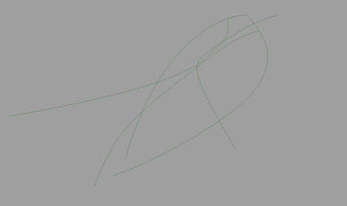
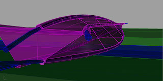
Once I had these curves I lofted them as straight sections rather than the normal curvilinear style and selected a closed loft resulting in this shape.
After I had this form I needed to make a place for the dowels to run through, so I used the pipe command on the same curves that I lofted and made them a 1/2" diameter and booleaned the loft and the pipe together.
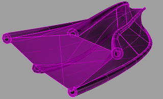
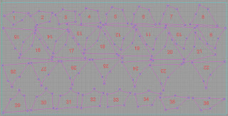
Then still using the same curves I once again used the pipe tool, but this time I made the pipe a 1/4" diameter and used the boolean-difference tool to make the 1/4" pipe hollow. Then I contoured the form ever 1 1/2" and layed it out for laser cutting.
This is also the project that I will be rendering in a architectural setting and here's the camera angle I'm rendering.
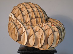
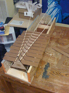
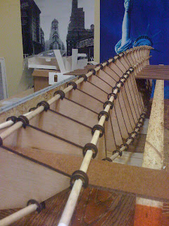
Building this was quite the treat. I took 5 1/4" dowels and 360 1/4" e-clips. The e-clips go on both sides of the vertical planes on all 5 dowels. I made a jig with spacers to get the correct 1 1/2" spacing between the contours.
So here is the final product in some sexy lighting
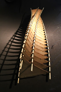
Monday, March 8, 2010

Andrew F. Scott | Mass >> Serial Volume


Andrew F. Scott | Mass >> Serial Volume
Originally uploaded by afsart

I created this form as a part of a video demonstrating the cut my ribs script by un didi. http://dimitrie.wordpress.com/2008/09/02/bridge-to-materiality/

Wednesday, March 3, 2010

Melissa March: Laser Cutting - Exercises

Goal: to explore the possibilities of the laser cutting by finding form through planar layers or serial construction.

Exercise One: Waffles
Create a surface form and construct it with a waffle structure. In class, Professor Scott showed us how to create a waffle structure using a grasshopper script. I created a surface by drawing several curves and lofting between them. The script did most of the work in creating the waffle structure, but it was customized by asking for input on material thickness and notching, etc. After going through this process, I laid it out for the laser cutter and cut my waffle structure out of cardboard.

Attempt One: the problem with this is that the form is a little too crazy. It would have worked better if I had more struts.


Attempt Two: this
one worked much better, but when you run the script remember to save it because you will need to refer to it when assembling. I tried to assemble it without referencing it, and it was very frustrating and didn't turn out right. Lesson learned: use script to assemble.


Exercise Two: Connection pieces
This exercise consisted
of first exploring forms with the pieces that professor Scott had created. After getting a feel for how it worked, he challenged us to create our own pieces. These are the pieces that I came up with.


And here are some forms that I generated with those pieces.


Monday, March 1, 2010

Melissa March: FDM Modeling - Project 2


Goal: to find a form through polygonal modeling, develop that form with techniques described in class, and produce an object with the FDM machine.


At this time we were ju
st learning Maya. We were seeing a wealth of possibilities open up with this software. Professor Scott showed us how to 'sculpt' in Maya using basic forms and manipulating them using simple commands (like scale, rotate, move, etc.). The form for my first project was not created using this sculptural process and I wanted to try my hand at it. As part of the lecture, Andrew showed us a honeycomb structure. Later, I created my own honeycomb structure.


I created this form by first making the basic cylinder in Maya (to the specifications that the FDM machine could print). Then I triangulated the faces and created the honeycomb. And LASTLY I found that I could play with the form of the objects by pushing and pulling the control points of the honeycombed cylinder with the soft select. The object turned out as pictured, it passed the 'closed form' test in rhino, approved by P. Scott and off to the printer!!

Or so I thought. Turns out there were some problem areas.

EXHIBIT A: See how the bottom edge is not touching the ground plane. Problem.

EXHIBIT B: See the 'rim' of the cylinder is all jaggedy. Problem.


So, even thou
gh my form had 'passed the test' it wasn't going to work the way it was. Back to the drawing board! Remember how I had adjusted the form AFTER I created the honeycomb? Therein lies the problem. When I did that and began adjusting the form some of the faces intersected themselves, which is a big no no. But one of the benefits of Maya is that is saves your history. Back in time I went, way back to the form as a cylinder, no honeycombing.

I then sculpted the form FIRST before doing the honeycomb stuff. This worked out much better. I also made sure that the cylinder touched the ground plane and that the 'rim' edge was smooth. And here's how it turned out.


As you can see, it's a little crankier than the first one. I played around a little more with the sculpting part and I think I came up with a more interesting form. One thing I did differently (that Professor Scott helped me with) was to show the polygonal form of the honeycomb. When you are modeling and adjusting the honeycomb, you see the edges of the triangulated faces. Well, I wanted that to be apparent in the final form, as well.


If you compare it to my first one (orange) the edges aren't defined. They are smooth (minus the voids of the honeycomb). But the final form (red) has those edges defined. It is a subtle difference but one I really wanted.
After my form was printed, I sprayed it with a good coat of clear coat so that the form would accept paint. I then painted it with a metallic spray paint because I wanted light to reflect off of it. From here, I will paint the outside a different color. I am thinking I will place a light source inside of the form because I think it would create really interesting shadows.