Sunday, February 28, 2010

Sunday, February 21, 2010
scpt250: w_2010 playday
scpt250: w_2010 playday
Originally uploaded by afsart
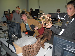
It was christmas on tuesday feb 16, 2010. all the milling projects were delivered. waffles were coming off the laser and fdm models were growing in the ddm lab. a good day to be a seven year old in scpt 250/450.
Wednesday, February 17, 2010
Melissa March: CNC Milling - Project 1

- Tetrahedron | 4-sided (Tetra = 4 )
- Hexahedron | 6-sided (Hexa = 6 )
- Octahedron | 8-sided (Octa = 8 )
- Dodecahedron | 12-sided (dodeca = 12 )
- Icosahedron | 20-sided (Icosa = 20 )
I chose to use a dodecahedron as my platonic solid. I chose this form because it consists of 12 regular pentagon faces. This means that I would create and develop one pentagon surface that I would later replicate twelve times. Finally, I will assemble all of these surfaces into one dodecahedron. My intention is for this dodecahedron to surround a light fixture.
Means and Methods: Rhino > CNC Millin
g Machine > Vacuum Former > Assemblage by Hand
I began developing the pentagon surface by starting in 2D. I figured out that to tessellate the pentagon I needed to subdivide it into five equilateral triangles. Each triangle in itself is a unit, which is rotated about the center. It is also crucial that each triangle is symmetrical about the base. This is important because the unit will not line up with another unit if this does not occur.
I chose four control points equally distributed along the edge of the pentagon. I named them A and B knowing that A and B will differ in location of the Z-axis. So, along the edge I have A, B, B, A. Point A occurs at ½” in the Z axis. The B c
ontrol points occur at 1 ½” in the Z-axis. I also had to choose where the vertices of the pentagon occurred in the Z-axis. Those occur at 1" in the Z-axis.
Once I understood the shape of my curve, I drew this in Rhino. I then copied and rotated this curve around the edges of the pentagon. From there, I lofted these curves. This was no easy task, as there were many intersections to deal with, but Professor Scott helped me to resolve these issues. We accomplished this by segmenting the problem areas with curves so that they could be lofted properly.


Production: Above, my pentagonal surface has been milled and is ready for the next step!
From here, I took my form
to the vacuum former. Next update will show the post production work and assemblage!


After I made these plastic forms, I used them as a molds to create these silicone forms. I used Oomoo (purchased at Ex Libris) to create these forms. What was really neat was that they picked up on the texture on the plastic and that translated onto the silicone form. With these silicone forms, I am free to explore other options without having to worry that I might ruin my original form.


So, after I created these silicone forms I created a composition using four of those forms and created a plaster mold for that composition. I will use this plaster mold to cast glass. I was very happy to see that the plaster picked up on those textural details, too!

Since vacuum-forming the hard plastic, I realized the the post-production work that would be required to turn those plastic molds into units of my dodecahedron was just too laborious and time-consuming. So I looked for other materials. One material that vacuum-formed incredibly was craft foam (found at Michael's). Though this formed great, I was concerned that it wouldn't allow enough light through (because I intend for my dodecahedron to form around a light fixture). With a flashlight, Professor Scott and I tested it and it did allow light to emit. So, back to the vacuum-former!


Here you can see my process: I stapled the forms together and discovered that I would need to make tabs to connect them to each other. The third image (above) shows that process and the tools I used.


Here's how I assembled this thing. I used small clips (from my fridge) to briefly hold the two adjoining units together while I stapled the tabs together. NOTE: the depth of the tab comes from the allowable space from the stapler. This was an important discovery. You can see I am using a baby stapler because it has the smallest profile, which allows you to staple very closely to the edge. I assembled piece by piece. While I was assembling, I learned that it HAD to be this material because it needed to fold in on itself at some moments to allow pieces to come together properly. A hard plastic would not have that ductility.


These images above show the pieces of the light fixture that I purchased for the light. I bought this way back when I was designing the milled piece in Rhino. I designed it so that the glass globe would fit into the dodecahedron - which means I created a mock up model in Rhino of the units forming the dodecahedron so I could size it properly. Here you can see that I needed to design a piece for the top of the hanging lamp. It was very important to design it in such a way that the light could still be disassembled so that it's possible to change the light bulb when needed.


The above images show how I treated the top piece and the finished product. Because this is a hard-wired light fixture I simulated what it would look like lit by using the pieces from a form about 80% connected together and fitted the opening around my desk lamp.

Tuesday, February 16, 2010
I thought this was inspiring:
http://www.flickr.com/photos/watz/sets/72157605938577977/
Happy fabbing!
- shannon
Monday, February 15, 2010
Andrew F. Scott: Mobius Strip Redux

This Maya solution to the Mobius Strip geometry is based on the same principle as those articulated in the original Mobius Stripped Posting. In this Maya solution The Twist deformation is combined with the Bend deformation to create the strip geometry. This solution provides a wide range of geometric expressions and aesthetic solutions to the Mobius Problem. Can you figure out how it is done???
Sunday, February 14, 2010
Urchin

Urchin
Originally uploaded by Inflatabill
Sarah Matthews,
I thought you might like this.
I hope this inspires your creative interest in inflatables
Melissa March:SCPT 250/450: Project1 Milling
SCPT 250/450: Project1 Milling
Originally uploaded by afsart
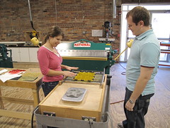
Melissa March begins to use her milled form to create the modular elements that will form her dodecahedron light form. While this may be her intention I think she may discover more applications for these unit forms.
Thursday, February 11, 2010
Carleigh Shannon:CNC Milling - Project 1
 Once the milling process is through, I plan to create a series of vacuum forms and shape them similarly to the picture below, with the potential of using more than four. The final product will be a wall piece.
 After receiving my CNC model and rubber model back, it was time for some smooth cast DOPENESS!
First five minutes:
 harding up at 6 minutes
 Ten minutes
 On to the next one after 15 minutes
Wednesday, February 10, 2010
Sarah Matthews: Project 1

For the milling and laser cutting assignment I wanted to recreate the crappy brick streets and sidewalks around Savannah. I felt this was a good concept since it dealt with a curved surface and a geometric shape. Unfortunately I could not make my bricks work for the population script in Grasshopper, but with the help of Prof. Scott we figured out a way to make it work. Instead of populating a shape onto a lofted surface as most people did, I used the CageEdit command. First I made a brick by lofting rectangles: two the same size for height and 1 slightly smaller for a beveled top. Beveling the top of the brick allows the bricks to appear to be separated. After making a roughly 18"X21" area with bricks in an L pattern there were square spaces along the edges where only half a brick is necessary. I took one of the bricks and 2-d scaled it so it was half the length of the normal brick and perfectly fit in the spaces. At this point I had a flat, bricked area, like the way streets should be: flat and smooth to drive on. Since Savannah is not smooth, I put a cage around the bricks using the Cage command. This creates vertexes which I can drag around and adjust the curves of the surface. This command is more gradual than lofting curves, but after completing the project I realized I didn't need curves that were any sharper. This allowed me to create a pothole and a few bumps in the road.
 After it is milled, I plan to mold and cast it in plaster. This way the bricks are more realistic. I will chisel cracks in the bricks just as bricked roads break and crack with pressure from roots moving below them. Then I will paint them and possibly throw more plaster over certain areas so it looks like there was an attempt to fix the bumpy surface.
Sarah Matthews:Project 2

I wasn't really sure what I wanted to do for this project. Basically I messed with the techniques Prof. Scott showed us in class and the tutorials. For some reason I was obsessed with spheres.
Every time I made a new project I started with a sphere and adjusted it from there.

After creating the sphere I selected staggered vertexes on the top half of the sphere. Then I scaled them to be larger. I didn't like the way they looked when they were roughly the same size so I went through each layer adjusting the scale of the spikes. Once I got those about the way I wanted Iseparated the sphere into 4 hemispheres. To make the hemispheres I selected 2 rings which intersect perpendicularly at the top and bottom of the sphere. The rings I selected were then scaled smaller so they are sucked into the sphere. I felt like the 4 points at the bottom would not be stable enough to support the structure so I pulled 4 of the spikes from the bottom layer down to form "legs" and create more support. I put the final touches on this project by adjusting the spikes to my liking. Some where scaled more, others were simply moved up or down.
Tuesday, February 9, 2010
Thomas Gibson:FDM Process

I continued looking at other generative structure ideas and came across something that wasn't exactly generative structures but it was more appealing to me with its capabilities than my previous idea. It was a grasshopper script that populated with two different tiles based on the tiles surface and its location to an angle in space. A full explanation and the script can be found here http://www.generativedesigncomputing.net/2009/11/rhino-grasshopper-modulation.html
After playing with this for a while I came across a form that I was pleased with.


So here is the final product turned out really nice. My Dad works at an aluminum foundry and I hope to be able to cast this in aluminum this summer

Chris Crowe: Imagined Landscapes
Much of this project stems from my interest in Sol LeWitt's work. Specifically his use of the grid in his projects and the way in which he experiments with solid and void constructions within this matrix.
 Sol LeWitt, (American, 1928-2007) ABCD 9 (Row), 1966, refabricated 1994 Painted steel. Platform and nine elements 20.375 x 102.25 x 30.5 in.
Sol LeWitt,(American, 1928-2007) Serial Project No. 1. (ABCD), 1966, Baked enamel on steel units over baked enamel on aluminum, 20" x 13' 7" x 13' 7" (50.8 x 398.9 x 398.9 cm). |
 Initial ideas about surface manipulation.
 Forming and separating the surface led to ideas about tiling.
 A surface was generated in Rhino so that it could be tiled across the floor to command presence in the room. The green lines represent the tooling path which will be followed while it is being milled out on the CNC. After the milling process is complete, a mold will be made of the surface so that many many plaster casts at different heights can be made to tile throughout the room.
 Just waiting until it gets milled.
 milled
_________________________________________________
SILICONE
The next step in the process was the application of a silicone mold to the cnc form.
First Layer

 Second layer of silicone
 After the silicone mold cured, a mother mold was poured by Professor Scott to support the bottom of the silicone. Then the pouring began.
__________________________________________________
Plaster
First plaster was mixed to the correct consistency, then it was pured into the silicone mold and allowed to cure while securing the edges with clamps so as to gain extra depth.
 After curing the silicone mold containing the plaster was removed, then the silicone was peeled away.
 After removing the plaster molds I used a rasp to hone the edges to be as clean as possible.
 Just kept at it and tiled away.
____________________________________________________
Sealing and Painting
After casting my tiles I then transported them to a friends house where I had full access to a spraygun as well as other shop equipment which is used for their business. First, the tiles were sealed with Killz primer. Two coats on each tile. After allowing them to dry, two more coats of a thinned out latex white paint was sprayed. I had to be pretty careful when spraying them as I did not want the paint to fill in the tool path which was in my plaster tiles.
one coat
 Two coats
Detail remains

As well as sealing and painting the tiles, I also constructed a base for my piece. The idea of the plane or base is to allow a visual extension of the piece into the space around it. I also slightly floated the base making it appear as if it is hovering above the ground plane, this dimensionality makes the grid of tiles which is very ordered a little more balanced as it contrasts with the loose floating feeling of the "heavy" base. I used the spray gun on the base after I built that also.

Tape was then applied in a grid so that i could have a framework to experiment with different tiling patterns.

 Float.